
ANSYS BLOG
March 24, 2020
Solder Fatigue Causes and Prevention
Solder fatigue is a major cause of failure in electronic assemblies over time and a serious concern across industries that manufacture electronics. As solder fatigues, it can result in solder joint failure, leading to a deformed or inoperable product that can negatively impact business, product development and time to market.
The primary cause of solder fatigue is coefficient of thermal expansion (CTE) mismatch, which results in fractures and open solder joints over time.
To learn more about the causes of solder joint failure, read: Top 5 Reasons for Solder Joint Failure or access the webinar: Ensuring Accurate Material Properties for Simulation with Digital Image Correlation (DIC).
How Does CTE Effect Solder Joints?
Coefficient of thermal expansion (CTE) is a material property that quantifies how much a material will expand or contract during temperature changes. Accurately quantifying CTE is vital to understand what materials to use when developing your product, determining the layout of the parts within your product and if a component is likely to encounter solder fatigue risk during its life cycle.
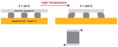
Classical solder fatigue illustration.
Excessive CTE mismatch between a single component and the PCB can cause lasting damage throughout the entire assembly. For example, the figure above shows a low CTE component soldered to a high CTE circuit board. As the assembly heats, the component shape remains relatively unchanged while the substrate expands and pulls on the solder balls in between. The opposite effect will occur as the assembly cools below its original unstressed temperature. Over time, as the temperature cycles from hot to cold — due to power cycling, diurnal effects or other system effects — the solder fatigues and eventually fractures.
A cracked solder ball can be caused by power cycling, diurnal effects or other system effects.
Over-Constrained Primary Circuit Boards
In addition to classic CTE mismatch, solder fatigue can also occur from over-constrained printed circuit boards (PCB) that have a significantly different CTE relative to their housing. This can result in excessive board bending during thermal excursions. Usually, this is caused by boards that are bolted into rigid metal housings, entering rugged environments such as aerospace or automotive applications.
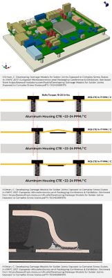
A model of PCBA and housing (top), an Illustration of an over constraint board in an aluminum housing (middle) and a broken solder joint (bottom).
For example, consider a board bolted into an aluminum housing. The rigid aluminum housing expands and contracts faster than the relatively flexible circuit board. As it expands and contracts, the housing may bend, adding stresses to the solder joints.
Understanding the mismatch between the PCB and its housing remains critical when assessing how a board may flex and bend during thermal expansion.
Glass Transition Effect of Potting, Coating and Underfill
The glass transition temperature of a material is the approximate temperature at which the material’s stiffness and expansion properties change. Above the glass transition temperature, the material is softer and more rubber-like with a higher expansion coefficient. Below this temperature, the material is stiffer and more glass-like with a lower expansion coefficient.
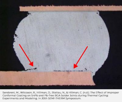
It’s essential to understand the importance of glass transition temperature when choosing materials and simulating it to evaluate solder joint reliability. For example, a cracked solder joint could result from the glass transition effect of an acrylic conformal coating that bridges the component body and board, sustaining damage at the end of the cold end of the thermal cycle. The acrylic has its glass transition at around 15C (59F). When it cools below this temperature, it becomes very stiff, crushing the solder joint and increasing damage with every thermal cycle.
Understanding the CTE and glass transition temperatures of these materials remains vital, especially if you plan to operate in a transition region.
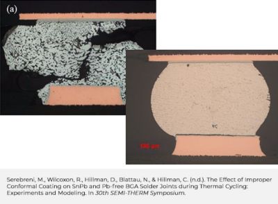
A cracked solder joint results from the glass transition effect of an acrylic conformal coating that bridges the component body and board.
Solder Fatigue Prediction
CTE-related issues can affect the reliability of solder joints during thermal cycling in a variety of ways. The effects are complex and are unlikely to be captured solely with design rules or engineering experience. Simulation can provide the solutions and methodologies needed to accurately predict solder fatigue risk within an electronic component.
At the board level, a common solder fatigue prediction methodology is the use of closed-form solder fatigue failure models, such as those included in Ansys Sherlock, a simulation software that uses physics of failure (PoF)-based electronic design to provide life predictions at the component, board and system levels in early stage design. The closed-form equations inside Sherlock account for component and PCB materials, component sizes, solder materials and other factors to rapidly predict solder fatigue behavior for all components in an electronic assembly.
At the component-level, detailed 3D simulation inside Ansys Mechanical, can be used to calculate the accumulated creep work in a critical solder joint of a single component during a thermal cycle. This output can then be used with a variety of existing powerlaw formulas to generate a prediction for the number of cycles to failure.
Whichever finite element analysis (FEA) method used, the solder fatigue predictions will not be accurate unless CTE inputs are correct. In the electronics industry, boards and component laminates often have complex structures whose CTEs are difficult to estimate without physical measurement. Ansys often conducts digital image correlation (DIC) measurements of CTE at the initiation of solder fatigue simulation activities to ensure accurate material property inputs.
Watch the webinar Ensuring Accurate Material Properties for Simulation with Digital Image Correlation (DIC) to learn how to accurately determine CTE and avoid solder fatigue risk using DIC.
Conclusion
Solder fatigue remains a major cause of failure in the electronics world. Most companies that design and manufacture electronics have likely experienced this issue. Accurately quantifying component and PCB CTEs and conducting informed thermal cycling simulations can provide companies with actionable data to determine if products face solder fatigue risk and what solutions exist to mitigate the risk.
Request a Free Trial to learn more about how Ansys Sherlock can help predict and mitigate solder fatigue.
See What Ansys Can Do For You
See What Ansys Can Do For You
Contact Us
Contact us today